It’s now time to physically build the sensor devices part of the nRF24 sensor network we are planning to build, so move to your electronics bench and pick some breadboards!
From an electronics point of view each sensor node consists of:
- 1 Arduino (any low-end model will do, I will be using two nano and one pro micro as this is what I have at hand)
- 1 push button
- 1 nRF24L01P module
- 1 1-100uF capacitor rated for 5V or more (usually, but not necessarily, electrolytic – any value in the range will do)
- 1 voltage source for 3.3V capable to deliver at least 20mA; viable options include:
- the
3V3pin of your Arduino board (available only on my two nano) - a voltage divider made by two resistors (I will use 100Ω and 220Ω allowing 50mA to pass through)
- the
WARNING While the module I/O pins are 5V tolerant (which makes this module compatible with practically every microcontroller), the module requires a 3.3V power source.
For absolutely no reason you should power the nRF24L01 module from a 5V source, unless you want to permanently damage your radio transceiver!
Please note I’m compromising here to keep things simple as the 3.3V source is definitely non optimal if you want to save on power consumption: for battery powered sensors you should be using 3.3V Arduinos, like the 8MHz pro mini, or an efficient voltage regulator like the AMS1117-3.3.
To keep the bill of materials at it’s bare minimum I’ll use the Arduino internal pull-up feature: this eliminates one resistor, but implies that pin 3 (the one attached to the button along with GND) will be HIGH when not pressed and turns LOW when pressed, just keep this in mind when we’ll start developing the sensors’ firmware.
NOTE These modules are quite sensitive to power line fluctuations and it should not be surprising considering they are radio transceivers operating in the 2.4GHz frequency: when transmitting data they require short but intense energy bursts to generate the electromagnetic field carrying the data. The capacitor we are adding should be as close as possible to the module in order to provide a local source of energy and avoid power fluctuations: it’s not an optional component!
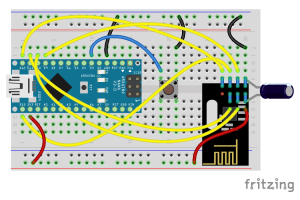
I will build 3 of those using, more or less, the following wiring:
If you wonder where I found the nRF24L01 Fritzing part, the answer is I made one myself (you can get it here).
Believe it or not, this is how these drawings turned into reality on my desk:
Now, the important thing to remember when wiring the modules, is they use a Serial Peripheral Interface, also known as SPI. What that means? Well, whatever board you are using to communicate to your modules, you need to identify the pins associated with the MISO, MOSI and SCK functions. Luckily for us their location is pretty well documented for Arduino and Arduino-like boards.
The modules use two additional I/O pins, called CE and CSN, but they are configurable so you can pick your own: I went for pins 9 and 10 respectively. Bear in mind though, if you’ll ever decide to change those pins, you will have to change the software accordingly.
NOTE Most microcontrollers have one single
SPIinterface, this doesn’t mean you can have only oneSPIdevice attached though! MostSPIdevices, including nRF24, have aCSN(Chip Select Not) pin which instructs the device to temporarily ignoreSPIcommunication, thus allowing for communicating with otherSPIdevices.
Testing
Now that you have your sensor boards ready, let’s move onto the software part.
You might want to use the Arduino IDE or, as I will, a more advanced solution like the Eclipse Arduino Plugin, an open source project I’m proud to contribute whenever I get the opportunity to. In case you decide to go for the Eclipse based solution, please follow the website instructions as not every configuration is supported.
I will use a few open source libraries trying to reduce the code to the real interesting parts:
- the RF24 from TMRh20 library is a fork of the original library from Maniacbug, who is no longer active
- my MicroDebug library, which I’ll use to provide some development feedback on serial console
Before getting your hands dirty though, it’s preferable to check your wiring with a known working firmware.
Among the many examples available in the RF24 library, the one I will use is RF24/examples/pingpair_ack.ino: this Arduino sketch is pretty simple and provides enough info to verify your setup.
There are just a couple of changes I’m going to make, to adapt to the above wiring, and I’ve marked them with comments in this Gist:
- the pins used as
CEandCSNare pins9and10, so line 24 has been changed fromRF24 radio(7,8)toRF24 radio(9,10)in order to reflect that - there’s no need to run the serial connection at
57600bps, so I slowed it down to9600bpsin line 41 - one of my boards uses the
ATmega 32u4chip (Leonardo and Micro use it), which means a board reset does not reset the serial connection; I need to wait for serial connection in thesetup()function to be able to check the module config, this required the addition of line 43
Once the changes are in place, upload the sketch onto the first sensor board and connect using the serial terminal. Don’t worry if you don’t see anything printed out, the addition of line 43 requires you to send something to unlock the setup phase.
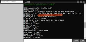
As soon as you send a character, you should see the following appear onto your screen:
|
|
As you can see the radio.printDetails() function call at line 59 provides tons of information: most will be blank (0xff) in case your module has not been setup correctly (99.9% as a consequence of bad wiring or false connections). If everything is setup correctly, you should see the addresses used at line 27 printed in the serial console.
Once you have verified the first module, leave it powered and move on to another one, but this time we will go a step further verifying the two modules are actually talking each other: if the second module reports a correct configuration send the character T on the serial and watch the two talking each other.
IMPORTANT When moving to verify the next board you must ensure to remove power to one of the other two, because this sketch uses and forces a linear network topology of two elements only: if you try to power up another one you will be unable to distinguish who is replying to whom.
In the next article we will look at the sensors’ firmware and how we can wireless notify the hub about the sensor’s button state change.


I definitely would *not* use such a voltage divider to get the 3.3V. The thing is that transceivers are *very* sensitive to unstable voltages. With such a voltage devider you might run into all kind of issues, especially if your 5V source is not that stable. Better use a 3.3V microcontroller or a good 3.3V power source.
LikeLike
Well, I partially agree with you and I believe I’ve said in the post I’m compromising here for sake of simplicity. The modules are sensitive to voltage variations, that’s the reason for the capacitor which provides enough energy to prevent the current spikes to reach the on-board voltage regulator. The voltage divider is a _good enough_ solution, proven to create no issue on my breadboards, but it will literally waste energy, which makes a really bad solution for battery powered sensors.
My personal choice would be a 3.3V board, but those are not as popular as the 5V ones and I don’t want to limit the readers.
Have you had problems using a voltage divider when paired with a bypass capacitor?
LikeLike
Yes, I had problems with that approach when other parts in the circuit were drawing sometimes more current. The result was that the voltage dropped sometimes as such that the nRF24L01+ needed a power-on reset to function properly afterwards. Adding around 200 uF capacitor temporarily fixed it.
LikeLike
As maybe many people will follow this usefull guideline, there’s a type halfway testing 1., should say from RF24 radio(7,8); to RF24 radio(9,10)
LikeLike
Hi Glenn and thanks for the correction: it should be now fixed. If you spot any error or convoluted/difficult to follow sentence please do not hesitate!
LikeLike
“Now sending 1 as payload. failed.” is the response I get from arduino if I dont remove line 43 on Nano.
while(!Serial.available()) delay(100);
Nano receives an address but will not transmit or receive transmission…
I hook up the receiver Nano to a battery. If I don’t remove this line in the receiver I get
Now sending 1 as payload. failed.
but I have to say I’m working with clone nano’s and they are not that reliable. Once I get them working they have no issues but to get them communicating is tough.
LikeLike
That makes a lot of sense. The issue is that lines puts your Nano “on hold” until you send a char to it, which actually breaks the portability!
Thanks for bringin this up, I’ll update the post and the code! I wasn’t experiencing the issue because I’m powering them all via an USB hub.
LikeLike
Have you ever used the nRF24lu1 ? it’s a usb key module (like any wireless mouse or keyboard). I received it today with some nRF24l01+. My goal it’s to upgrade a pro micro gamepad to wireless, but i think it will be a long hard job. It’s hard to find any document or guide about this module.
LikeLike
Sorry, never seen one
LikeLike
I had a quick look at the datasheet and it seems very similar to the nRF24L01, the “non plus” version: I believe the biggest difference is this module has USART embedded, meaning you can program/communicate directly via USB, but it is reported being “air compatible” with the L01.
It should have a bootloader already on it, but I can’t help on how it can be programmed via USB
LikeLike
i tried to this. but all the connections dropped after connect capacitor. what can i do.
LikeLike
Please, consider I’m not sitting beside you: I need more info to provide help.
I understand English is not you main language, but if you don’t put any effort in describing the details I have no reason to spend even a minute trying to answer.
Anyway, the best place to post a request for help on NRF24 is on https://arduino.stackexchange.com/ not the comments section of a blog.
LikeLiked by 1 person
nice reply. thanks
LikeLike